How to Modify a Sinclair Q2220E
132-174 MHz Duplexer to 220 MHz
by David Cameron - VE7LTD
IRLP System Designer - http://www.irlp.net
Date: February 6, 2007
Update September 11, 2009 (sweeps)
Required Supplies
| Tool or Supply | Purpose |
| tape measure | length measurements |
| permanent marker | marking position of loops and high/low pass |
| calculator | calculating scaled lengths |
| solder | all solder connections |
| propane torch | soldering/desoldering of finger stock, and removing plastic stopper plugs |
| desoldering suction tool | desoldering of coax connectors |
| desoldering braid | desoldering of coax connectors |
| pipe cutter | cutting the internal tubes |
| hacksaw | cutting the excess rod length |
| reversible electric drill with # 2 Robertson bit | removing casing screws |
| flathead screwdriver | opening connectors and removing finger stock |
| Philips screwdriver | removing loop tension screws |
| 7/16" wrench | loosening lock nuts |
| small pliers | loosening crimp rings |
| small hammer | removing finger stock |
| 3/16" drill bit | re-rounding crimp rings |
| hex crimping tool with 0.213" die | crimping rings |
| small half-round edge file | smoothing burrs |
| soft cotton cloth | buffing oxidation, and general cleaning |
| pencil with pink eraser | cleaning finger stock contacts |
| 5/16" Redi-rod | removing plastic stopper plugs |
| two part epoxy | re-attaching foam blocks |
Optional Supplies
| Tool or Supply | Purpose |
| 4 silver crimp rings for RG-142 | replace old crimp rings |
| heat shrink tubing | cleaner looking crimp connections |
| silver solder | recommended for mechanical solder connections |
Required Time - approximately 2 to 3 hours
Disclaimer
The modification below is provided as is and for information only. This particular modification worked well for me and produced a 220MHz duplexer that exceeds the specs for a Sinclair made Q2221E. I accept no responsibility for errors or problems you may encounter during your modification.
Background
The Sinclair Q2220E is only a good repeater duplexer for a 144-148MHz amateur band when you are running low power. The duplexer offers only 70db of isolation at 600kHz frequency split, which, in my opinion, is not sufficient for anything solid state over about 20 watts, especially if you use a preamplifier. That being said, Q2220E duplexers are working just fine on many ham repeaters. The Q2220E has two separate harnesses available: 132-150 MHz and 148-174 MHz. Either harness will work in the ham band, but the lower split harness provides lower loss.
70dB isolation was not enough for my repeater, and I was not in need of another 144 MHz duplexer. What I did want was a 220 MHz duplexer, so I decided to modify my high-split Q2220E to 220 MHz. Sinclair sells a Q2221E for 220-225 MHz band, but the cost was too much for my ham budget.
To start my modification, I did some research and calculations. I knew that most parts needed to be scaled down in size to work at 220 Mhz. This included the tuning rods inside the cavities, and the phasing harness. The inductive loops, tuning capacitors, and duplexer casing do not require modification. PICTURE
As with any modification project, you should verify proper operation on the original band before starting the modification. If the duplexer has internal damage, it may not tune correctly.
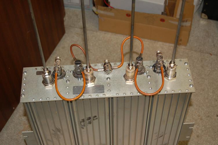
Modifying the Phasing Harness
The first thing is measure the phasing harness for length before you start. The length of the RG-142 B/U coax between the cavities should be an electrical quarter wavelength, as should the length between the cavities and the T-connector. To properly determine the length in coax (L), we must multiply the length by the velocity factor to get the actual length of coax. The velocity factor (VF) of RG-142 B/U is 0.695. The existing harness had 12.75 inches length from cavity to cavity and from cavity to T-connector. To figure out the frequency (f, in MHz) associated with this length we use the following formula:
This yields a resonant frequency of approximately 161 MHz, which is about halfway between the designed frequency range of my harness (148-174). Please do your calculations with your harness, as some of the harnesses used over the years have changed both in length and the coax that is used.
To modify to 220MHz, you have to shorten each cable to center it around 224 MHz. When you flip the equation around to solve for length, I found an optimal length of about 9.15 inches. So you have to carefully remove about 3.6 inches (or more depending on your harness) from each length of the phasing harness.
Note: You will only need to desolder and cut the coax feeding into the two connectors that are not the ANT, high-pass (HP), or low-pass (LP) ports. That way you only have to desolder/solder two connectors to shorten all of the coax lengths. If you number the 5 connectors from one end of the harness to the other, you only have to desolder numbers 2 and 4.
(HP-1) ---- (2) ---- (ANT-3) ---- (4) ---- (LP-5)
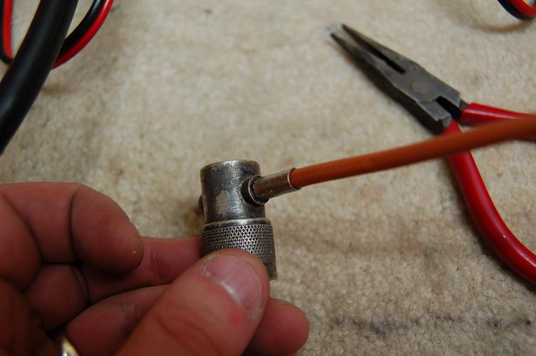
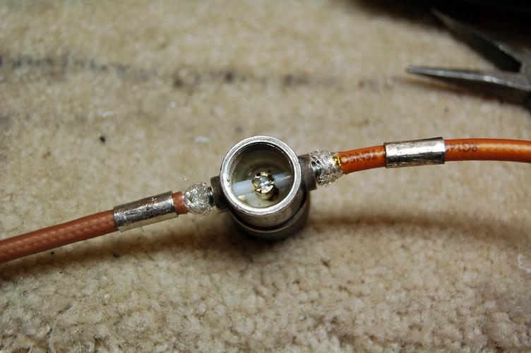
To accomplish this, carefully work the existing crimp rings round again with a pair of pliers until they are loose. Using a flathead screwdriver, unscrew the top of the T-connector and unsolder the center conductors of the two pieces of coax from the connector. You will need to use a solder braid and/or suction device to remove all of the solder. Once free, carefully pull the coax out of the T-connector. If the coax does not come out easily, keep working the crimp ring. You do not want to break any part of the connector. PICTURE PICTURE PICTURE PICTURE
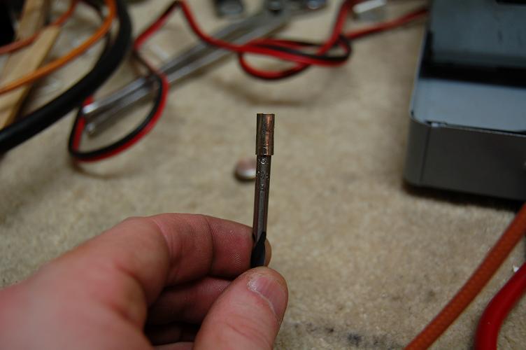
If you don't have spare silver crimp rings, use a 3/16 inch drill bit and press the removed crimp ring onto the smooth end of the drill bit, to round the edges of the crimp ring and it can be reused. PICTURE
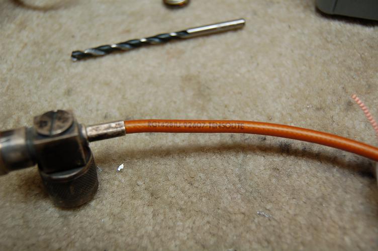
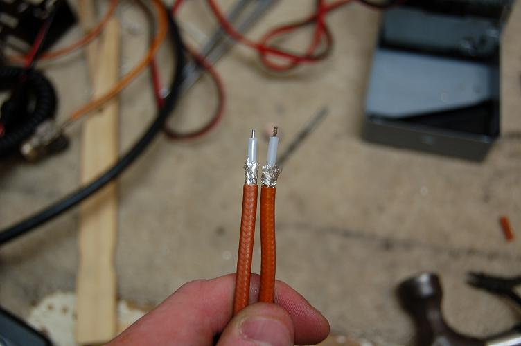
Use the removed coax pieces as a guide to how you should prepare the shortened pieces for re-solder and re-crimp onto the connectors. Remove 3.6 inches (could vary for your harness, do your own calculations) from each length, and prepare the ends for re-assembly. PICTURE
When re-assembling the phasing harness, solder the center conductor of the coax to the connector. Be sure that no solder bits are loose inside the connectors when you are done. These could flop around and short out the RF inside the connector. Also, use a quality hex crimping tool to reattach the crimp rings to the connector to ensure a good crimp for years of reliable service. You may also want to add shrink wrap onto the outside of the crimp ring for a nice clean look. If you can not get the crimp rings tight, you should replace them or you can also apply solder to the rings and solder them right to the connector, without too much risk of melting the teflon coax. PICTURE PICTURE
Modifying the Internals of the Duplexer
Using a pen, clearly mark the location of the high pass and the low pass side on the top plate and side of the duplexer. Although not crucial, it will make re-assembly easier. Also number and mark the position angle of each of the connector/capacitor loops. Putting them back in their original positions will make final tuning easier.
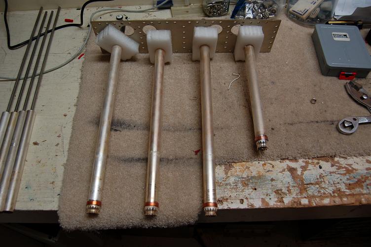
Using a drill, remove all of the 60 or so No. 2 Robertson head screws on the top of the duplexer. If you don't have a drill, get one. The bottom screws can be left alone. There are four foam blocks that help support the center tubes. Push the blocks up the tubes (they dont need to be removed) for later re-attaching.
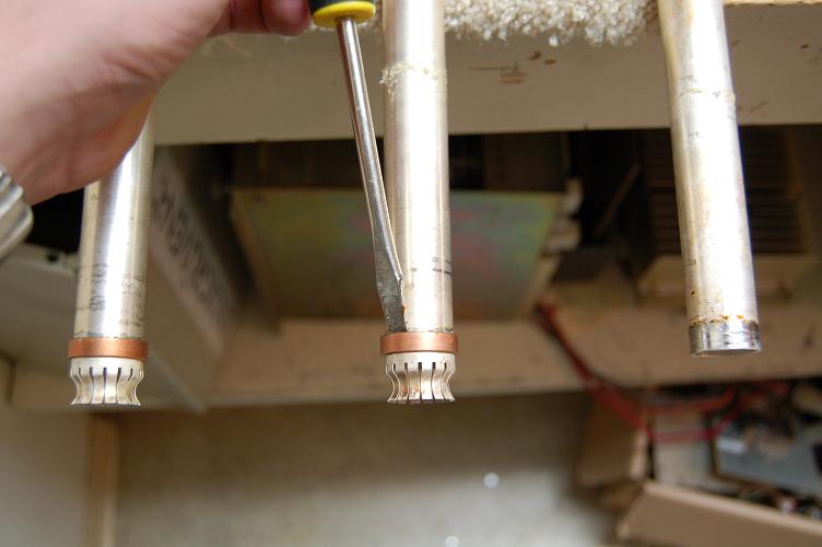
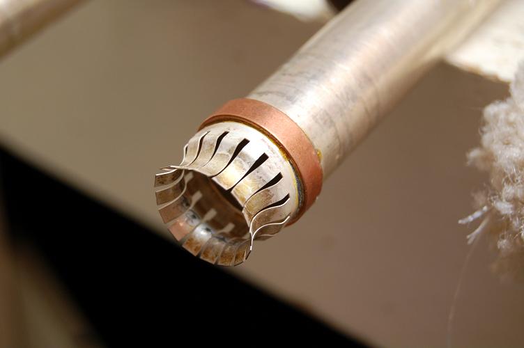
The only other parts that require modification are the internal tuning rods located inside the duplexer. There is a silver plated "plunger" that moves in and out of a silver plated copper tube to provide precise frequency tuning. There is silver finger stock on the base of the tube that provides a solid electrical connection. The finger stock is soldered onto the tube using a copper ring.
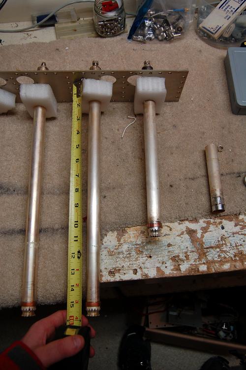
These quarter wave stubs also have to be shortened for 220 Mhz. The exact amount they are shortened is not that crucial as long as the tuning plunger can still tune within the range 220-225Mhz. The tuning length of the tube/plunger will be around 13 inches, so I cut my tubes to be 10 inches from the top plate to the end. With the finger stock, the tubes will stick out about 2.5 inches.
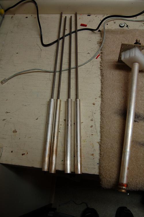
The first step is to remove the rods and plungers from the duplexer. Loosen the top nut on each rod, and remove the protective red end caps (if attached). Ensure there are no large burrs on the top of the rod where it may have been cut to fit. If it is not smooth, use a file to smooth it out. Pull the rods out the bottom and set them aside. PICTURE PICTURE
Using a torch, carefully heat the ends of the tubes and remove the finger stock and the copper ring. Some important warnings here:
Since we are cutting off the bottom of the tubes and I don't care about damaging them, I use a flathead screwdriver and a hammer to tap the ring and finger stock off in one piece together. PICTURE PICTURE
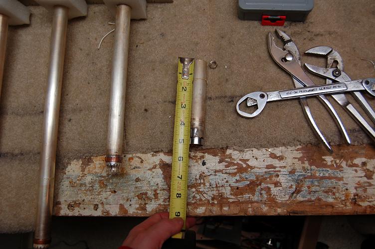
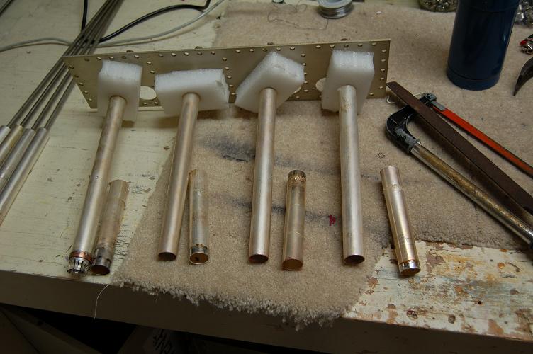
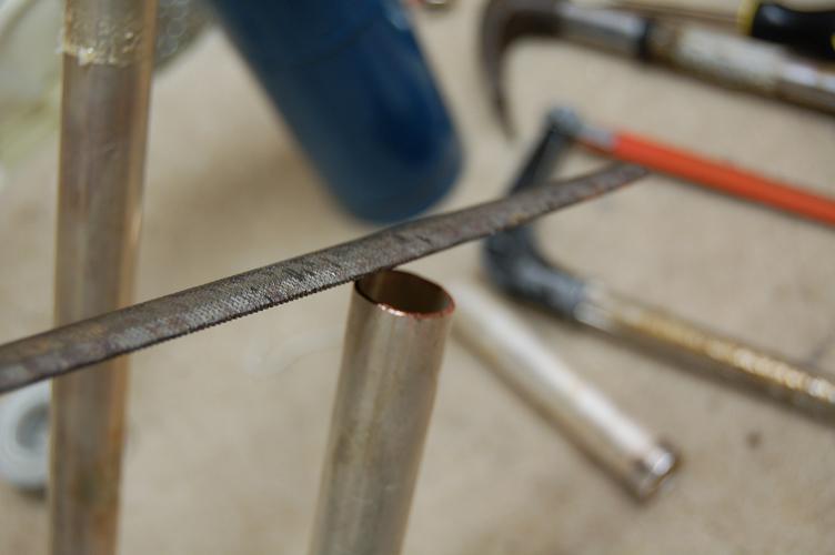
Next, decide how much of the tube you want to cut off. The stock tube for VHF is about 15 inches long. I cut about off 5 inches which allows my duplexer to tune between 170 and 250 MHz. The best tool to use to remove these is a pipe cutter, but a hacksaw can be used as well. The more you remove, the easier the next step will be. PICTURE PICTURE PICTURE PICTURE
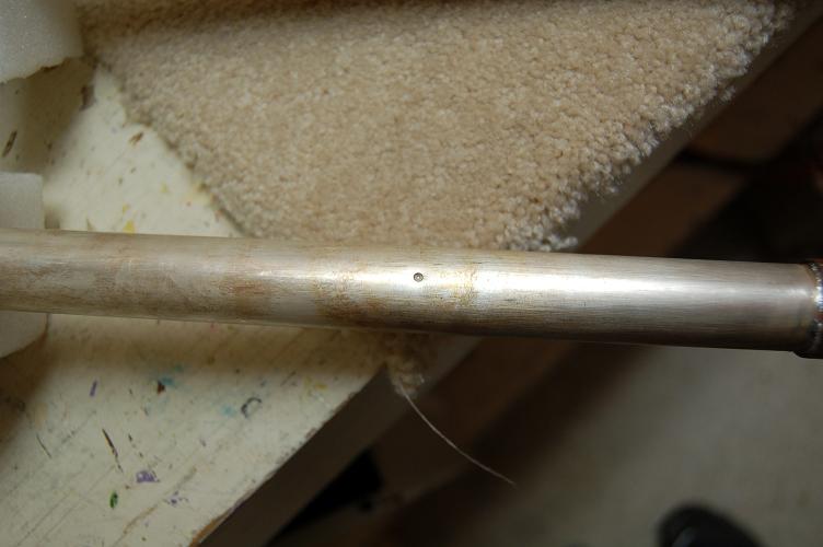
There in one major "gotcha" in the design that limits the ability to easily tune to 220 MHz. Located about 3 inches up the cut silver plated copper tube is a plastic stopper plug that is designed to center the rod in the tube as well as limit the upward travel of the plunger. This plug is made of plastic and is held in place by a small divot that is punched into the side of the tube.
This plug must be pressed upwards or removed downwards to allow the plunger to travel up far enough into the tube to tune to 220 MHz. I removed mine by using a piece of 5/16 inch "Redi-rod" from a hardware store. It is essentially a steel rod that is threaded from end to end. The diameter was large enough that it threaded tight into the plug, which made it easy to pop out the bottom of the tube with a little force. I used the propane torch and applied a little heat around the plug to soften the plastic. Don't try to remove the plug before you remove the finger stock as you may damage the fingers. Alternately, you can also push the plug up and into the tube, as it is thin enough not to affect the tuning rod at 220 MHz lengths. The disadvantage here is that you have the plugs loose inside the tubes. PICTURE PICTURE
Depending on how strong the Sinclair tech was who built your duplexer, the depth of the divot may interfere with the sliding of the plunger up and down inside the tube. You may have to use the round edge file to smooth some of the divot so it does not scour the tuning plunger during tuning. I did not have to file any of my divots, but they were close. PICTURE
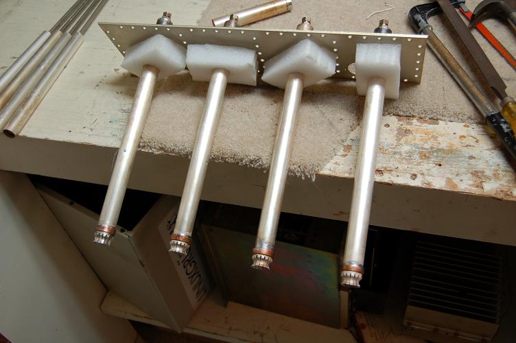
Once the tubes are cut to length, remove any burrs from the inside and outside of the tube with a file. I also found that the edges of the cut end of the tube had to be rounded a bit to place the finger stock and copper ring back onto the end of the tube. I removed a bit of the copper around the edge of the tube with the "teeth" of my pliers. Position the finger stock square onto the end of the tube. Using a torch, heat the tube and solder the finger stock and ring back into place using solder. I recommend silver solder here if you have it. PICTURE PICTURE PICTURE
Using a pencil's eraser, carefully clean the contact points of the finger stock. Using a soft cotton cloth, rub any oxidation, finger prints, or solder flux off of the silver components, including the tubes and the plunger. Do not use anything too abrasive, as the silver plating is very fine. Do not use silver polish as the finish it leaves behind is not conductive.
The length of the casing has little effect on the tuning of the cavities. The casing can be left alone, or can be cut to shorten the overall length of the duplexer. The Q2220E is 24 inches long. The Q2221E (for 220 Mhz) is 17.25 inches long from top plate to bottom plate. Cutting the duplexer adds a layer of complexity, as you will now have to remove about 40 more screws, as well as re-attach them (self-tapping) after the cut is complete. You will require the use of a large metal bandsaw to do the job right. You will have a few leftover parts which you removed from the duplexer. PICTURE
Re-assemble the duplexer. Using some epoxy, glue the foam blocks onto the tubes about an inch from the finger stock. When the epoxy has set, put the two parts together, paying close attention to the high pass/low pass relation marked earlier. If the screw holes do not line up, don't force them. Instead, lift the top plate out, re-align the foam blocks, and re-insert. Insert and attach the loops into the duplexer using the same orientation as when they were removed. Attach the harness. Tune the duplexer using whatever means you use. There are tuning instructions for the Q series duplexers that can be found on the internet. Once tuned, determine the length of tuning rod you want to keep exposed and cut the remainder. Like the case, you do not have to cut the rods, but it makes the whole installation much cleaner.
When tuning the duplexer, you will want to adjust each loop individually to set the insertion loss.
I found that approximately 0.5 db pass loss yielded about a 40 db notch at 1.6 MHz separation.The following
scans were obatined from my HP8920A service monitor.
High Pass Pass - 224.000 Mhz
High Pass Notch - 222.400 Mhz
Low Pass Pass - 222.400 Mhz
Low Pass Notch - 224.000 Mhz
That's it! You should now have a fully functional duplexer for the 220MHz band that meets the specifications of a factory Q2221E.