|
|
IRLP Link Radio
Interface and
|
|
IRLP - Keeping the Radio in Amateur Radio |
|
|
Those Radio Amateurs desiring a Plug-N-Play radio should consider some of the used very reliable ex commercial units such as the Motorola and GE models described here. Yes you will need to make up a simple cable for the GE and Motorola radios but hey! - you're a licensed ham radio operator so this simple project will be a breeze.
If you are challenged at this, please post your questions to the IRLP Groups.io group https://groups.io/g/irlp/
Please do not waste a perfectly good dual band mobile or HT or worse yet a multi band/mode HF rig. We received almost daily queries about adopting IC-706 and FT-847 radios. Look on eBay or your neighbourhood Hamfest for one of the following bargains that make outstanding reliable node radios.
NOTE: While surplus commercial radios are by far the best choice for IRLP nodes, ALL commercial rigs require proprietary programming software and hardware. While there are many sources in most communities for this type of programming, it is best to check first with your area ham buddies who work in the commercial field before acquiring the rig. Barring that, you can expect to pay between $30-50 to have a couple of channels programmed at a commercial shop.
MOTOROLA M SERIES RADIOS
with 16 pin option connector
You should check eBay for the following search words. GM300, MAXTRAC, M120. You must make sure the radio has a 16 pin option connector. The 5 pin radios DO NOT have COS at the plug .
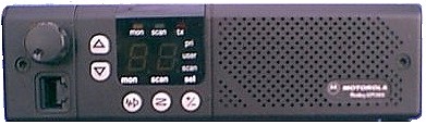
GM300 shown here
Pin -Outs for ALL Motorola 16 pin radios
TX audio in=2 * a 10UF Non-polarized DC blocking cap in series may be required
PTT = 3
Gnd = 7
COS = 8 active low on carrier or valid PL
NOTE: on 16 & 32 ch models, this pin is
programmable for other functionsRX audio out = 11
NOTES:
-
As long as the microphone is inserted and hung up on the clip, the PL will be enabled. To operate the node without a microphone plugged in, make an RJ45 mic plug shorting the PL line (PIN 3) to ground (PIN 4). To enable the front panel speaker, jumper 15 to 16
-
On most of the Maxtrac radios, the feature which forces PL to be enabled when the microphone is hung up (clip button on back of microphone grounded) can be DISABLED when programming the radio. This is under the radio-wide options screen along with the TX timeout value which can be set to OFF. Neither of these are default settings. TNX Bob AC0KC
Useful Motorola Links
LOOKING FOR A PRE-MADE CABLE?
CLICK HERE
for pre-made cables from Marshall KE6PCV
A great resource for Motorola Radios including 5 pin Radius models can be found at Batlabs www.batlabs.com . Model specifics can be here........ http://www.batlabs.com/2way.html
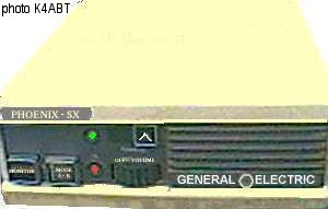 GE
PHOENIX
(S or SX models)
GE
PHOENIX
(S or SX models)
by Rob N1NTE
The GE Phoenix radios make nice IRLP simplex nodes.
Normally, a Phoenix puts out around 25 W on UHF up to 40 W on VHF. If you
are not planning on using a fan on the heat sink, then it is recommended
that you turn the RF power out down to about 10 watts. The power out
potentiometer is R120 located on the bottom of the radio under the metal
shield. There is a hole in the metal shield that allows you to gain access
to it.
Here are the connection details:
There are two connectors on the back of the radio - J911, the microphone
plug and J910, the power/speaker plug. J911 is an 8-pin connector and J910
is an 11-pin connector. If you are looking at the top of the radio with the
rear facing you, J911 is on the left and J910 is on the right. (See diagram
below)
Pin 2 on J911 is the PTT
Pin 4 on J911 is the TX audio
Pin 4 on J910 is the RX audio
Pin 2 in J910 is the COS (active hi (10v) on valid CTCSS tone)
Pin 8 on J910 is GROUND
Below is a diagram. Notice that you need to add a diode in series with the COS line and its polarity. The shield of the cables connecting the sound card should be connected to ground.
Thank you to Paul Cassel, VE3SY for the original post to the IRLP General email list detailing the hook up information. Please send corrections and modifications to Rob Bellville, N1NTE n1nte @ cox . net
An Improved Interface for GE Phoenix RX audio
The above interface requires very minimal knowledge of electronics however the audio transmitted FROM your node to the network will be thin with few lows. This is due to the fact there is no de-emphasis being performed. This can be over come by taking audio direct from the speaker terminals and keeping the speaker audio very low so not to overdrive it.
A better solution is to use the simple circuit below from Sean N0PBA of IRLP node 3239 which not only provides the needed de-emphasis but also adds some audio gain to make up for the low level from the radio. This circuit would be added in series with the line from Pin 4 of the radio to the Line-IN of audio card. The 12 VDC can be tapped into Pin 1 or 11 both of which usually have 12 VDC from the power plug.
Useful GE Resource
http://www.rtzaudio.com/kg4lne/phoenix.asp
|
|
Find an Phoenix radio on eBay |
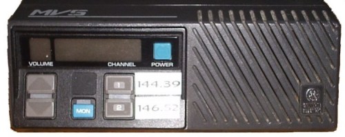
GE MVS IRLP Wiring Instructions
by Warren Paulson VE3FYN
email: ve3fyn at shaw dot ca
![]() Marshall -
KE6PCV has UHF
MVS radios ready to go with cables.
Marshall -
KE6PCV has UHF
MVS radios ready to go with cables.
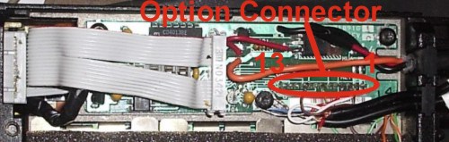
The option connector is found by removing the metal plate from the bottom of the radio. Two Torx screws hold the plate on. With the plate removed, locate the 13 pin option connector, near where the power cord enters the radio. Pin #1 is closest to the back of the radio. Note that the GE-MVS manual refers to pin #10 on the MVS as an audio mute pin. However this pin generates 5 volts DC when a signal is detected, making it useful as a COS pin.
Download the PDF original GE MVS manual here. This will provide operating information, and in-depth background to the mods shown here, including block diagrams and schematics.
|
DB 9 Connector Wiring
|
|
Audio Jack Wiring
|
|||
|
DB9 pin
|
MVS pin
|
Description |
Line in jack
|
MVS pin
|
|
|
1
|
.
|
not used
|
Ground
|
Ground*
|
|
|
2
|
7
|
PTT out
|
Middle Ring
|
not used
|
|
|
3
|
.
|
AUX1 out
|
Tip
|
3
|
|
|
4
|
.
|
AUX2 out
|
|
|
|
|
5
|
.
|
AUX3 out
|
Line out jack
|
MVS pin
|
|
|
6
|
Ground*
|
Ground
|
Ground
|
Ground*
|
|
|
7
|
10
|
COS in
|
Middle Ring
|
4
|
|
|
8
|
3
|
Audio to DTMF
|
Tip
|
not used
|
|
|
9
|
.
|
not used
|
|||
Ground DB9 pin 6, and audio jack ground to one of the screws near the option connector. Ensure that the radio and your computer share a ground.
From the point of view of the MVS Option Connector, the connections are as follows:
|
Option Connector Wiring
|
|
|
Pin #
|
Use
|
|
1
|
not used
(Can be used to provide 12v power) |
|
2
|
not used
|
|
3
|
Audio out to DTMF
Audio out to line-in |
|
4
|
Audio in to line out
|
|
5
|
not used
|
|
6
|
not used
|
|
7
|
PTT signal
|
|
8
|
not used
|
|
9
|
not used
|
|
10
|
COS signal
|
|
11
|
not used
|
|
12
|
not used
|
|
13
|
not used
|
|
Ground
|
Ground DB9 #6 and audio jacks to the radio chassis.
|
Audio Levels
On at least some MVS radios (apparently not all),
changing the volume will change the output level on pin #3. If this is the
case with your radio, set the volume level where you want it for proper
audio levels into the computer, and leave it. I have found this on some GE-MVS
radios but not all, and have yet to correlate this effect to certain model
numbers.
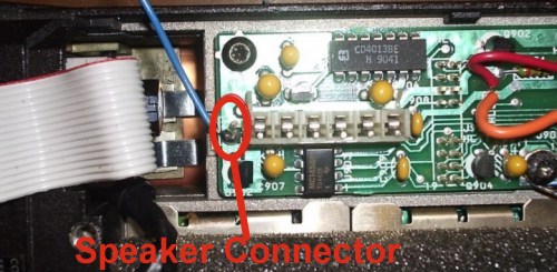
On those MVSs with fixed audio output, you may find that the audio level is
too low. To boost your audio output, follow one of the two suggestions
described in the "Improved Interface for GE Phoenix RX audio" section on the
IRLP website. If you are going to take audio off the speaker (the simplest
approach) the following photo locates the speaker connection.
|
|
Find an GE MVS radio on eBay |
|
|
 ALINCO
DR-135T
- 144 MHz "D" model
requires removal of TNC
DR135T/E MkII
DR-235T - 222 MHz
DR-435T - 440 MHz
 These
Alinco models have a DB9 connector designed for packet radio and work quite
well for IRLP. Pre-made cables are also available from the
following sources
These
Alinco models have a DB9 connector designed for packet radio and work quite
well for IRLP. Pre-made cables are also available from the
following sources
Marshall KE6PCV at http://www.irlpcables.com
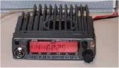
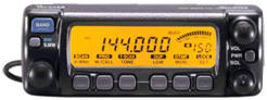
KC2IVI - IRLP 4889 RADIO IC-207H
The Icom 207H Dual Band
 Single Display has been operating as my node
radio for over 8 years now. This is an ideal choice for
Simplex Nodes as you can operate on VHF
or UHF.
Single Display has been operating as my node
radio for over 8 years now. This is an ideal choice for
Simplex Nodes as you can operate on VHF
or UHF.
 As a link radio to a repeater, this radio works well. I find it
useful to be able to switch to a Simplex frequency for troubleshooting and testing new scripts.
As a link radio to a repeater, this radio works well. I find it
useful to be able to switch to a Simplex frequency for troubleshooting and testing new scripts.
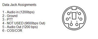
Above are the Data Terminal pinouts. The IC207H has 2 Data in settings. 9600 bps should NOT be used. The instructions for setting the data speed is included below.
I used an old PS2 mouse, cut the cable and made the necessary connections to the computer and sound card. I do not have an actual diagram for the cable I made, but it should not be hard to make.
NOTE: This setup will also work with other ICOM radios such as the IC-2720
Other Radios
If you have detailed info on radio interfacing please drop the
webmaster a line at
|
Enjoy IRLP and please "Pass the Word" If left menu bar is not visible, click here |
||
|
last
updated
August 06, 2011 |
||